
Loop test for valve pressure and heat shock
Closed-circuit test bench designed to test hydraulic valves for the energy and nuclear sectors. Loop test for valve pressure and heat shock
THE SOLUTION PROVIDED BY LF TECHNOLOGIES
Main functions
Objective
Design and production of a pressure and temperature test loop for valves and fittings.
The test loop must simulate a circuit in which water circulates at a high flow rate (300 l/min), under high static pressure (270 bar), with large and rapid temperature variations (from 20°C to 285°C).
The system must be capable of controlling the actuation of automatic valves (electrically or pneumatically operated) or of operating manual valves with a controlled and measured torque.
The bench must be suitable for a wide range of valve sizes, and enable them to be easily fitted to the system.
User safety is an essential issue, particularly in relation to the problems of pressurised superheated water.
The bench control must be ergonomic and must enable automatic and configurable test procedures to be carried out, making it easy to use.
Problematic issues
Solution and result
The proposed system consists of 2 test loops (1 hot and 1 cold), which use a set of valves to circulate hot and cold water alternately through the valve under test (thermal shocks). The hot circuit is heated by a pressurised thermal cartridge, while the cold circuit is cooled by a special, custom-designed heat exchanger.
A set of servo-controlled plungers adjusts the static pressure of the loops, enabling a pressure difference of up to 270 bar to be applied to a closed valve.
Circulation flow is ensured by 2 special, custom-designed circulators, delivering flows of up to 300 l/min.
Manually-operated valves are operated by a servo-reducer with torque control from 5 to 1000 Nm.
The circuit’s dimensional flexibility is ensured by a set of patented self-sealing swivel fittings, custom-developed by LF Technologies.
Fixing the valve under test is made easier by the use of a removable bracket.
The operator installs and clamps the valve on the removable support, then positions and locks it in the test area. It connects the valve ports to the water inlets and outlets. It couples (or electrically connects) the actuator. The doors are then closed manually and locked automatically. A Human Machine Interface (HMI) is used to create and record test routines. The test can be started.
Products testedA control PC, using software developed under LabVIEW, performs the control and measurement functions.
Small valve tested before assembly on the machine
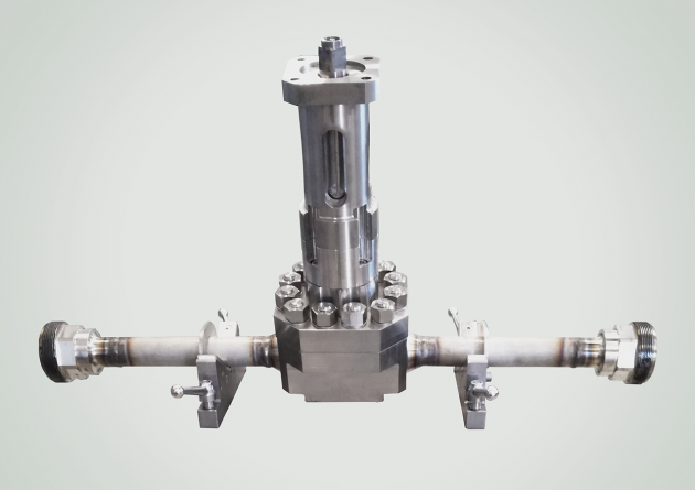
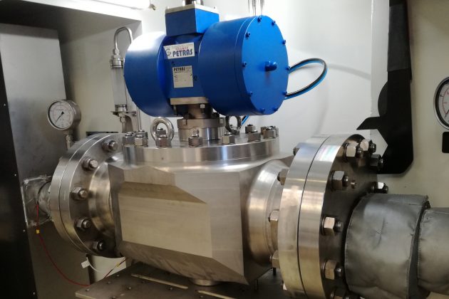
Valve tested
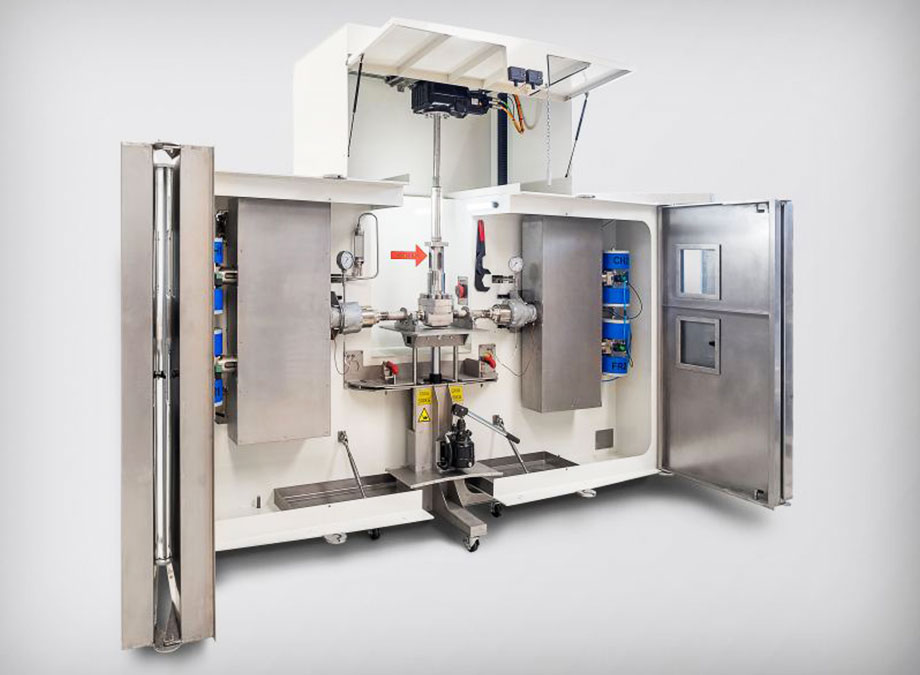
Test benches for industrial valves
Test benches for industrial valves
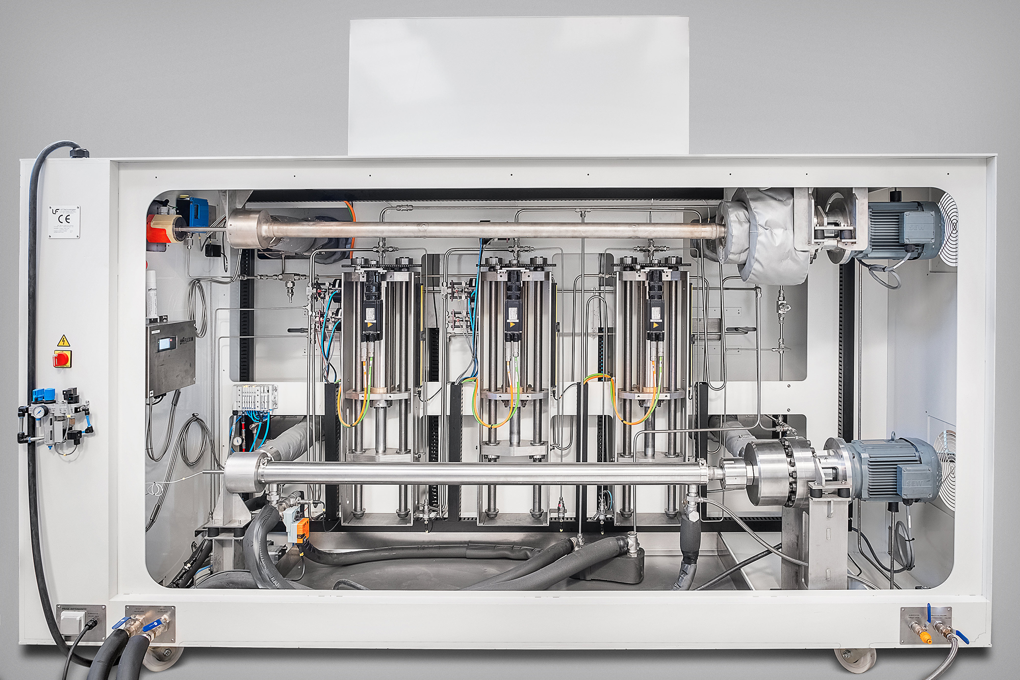
Pressure control system
Pressure control system
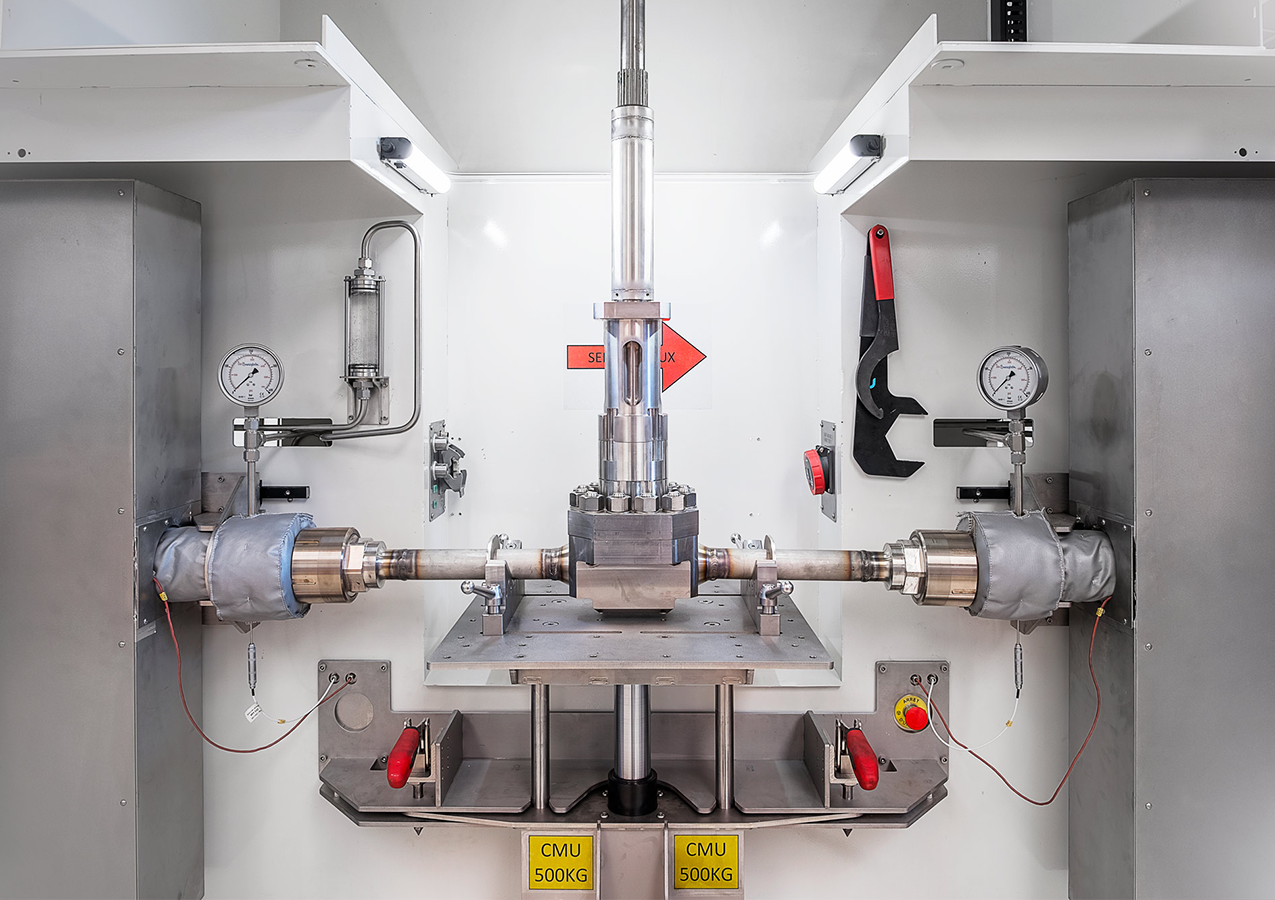
Pressure test loop test zone
Pressure test loop test zone
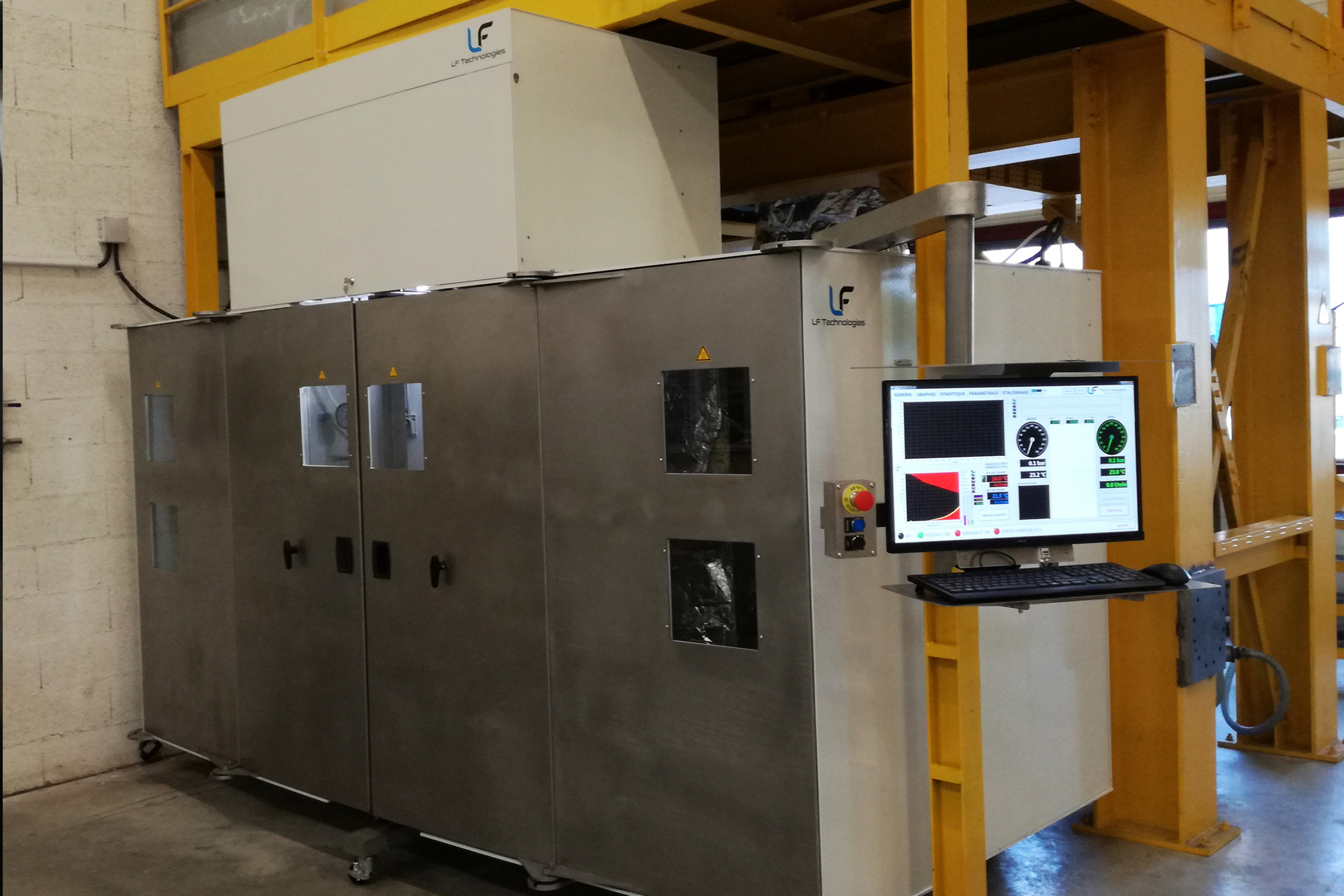
Customised test loop installed on site
Customised test loop installed on site
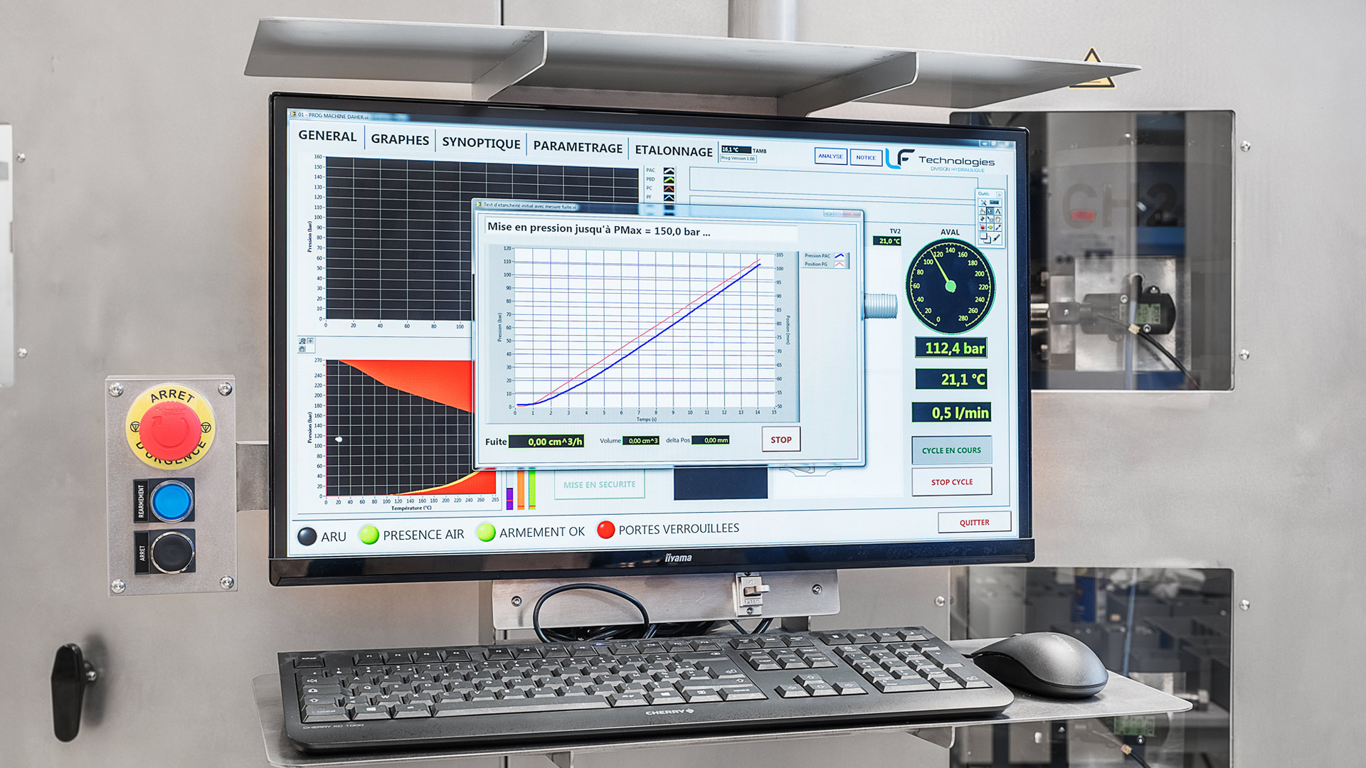
Test loop test curve
Test loop test curve
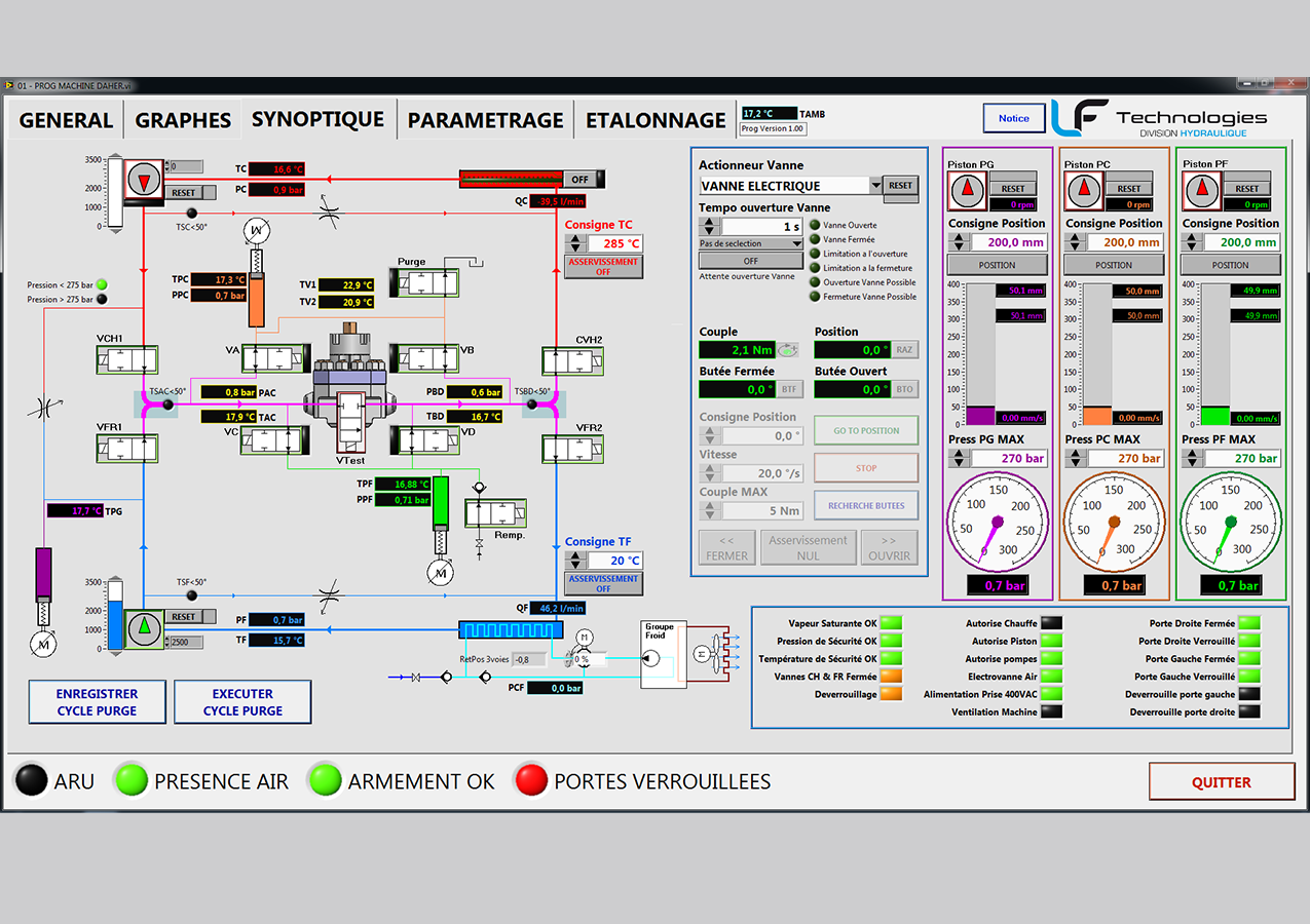
Valve test loop diagram
Valve test loop diagram

Do you have a project in mind ?
I'm here to advise you and propose solutions tailored to your needs.
Aurélien Cottin
Hydraulics Division
Other sector applications
Discover other test benches and special machines designed and built by LF Technologies.


